The following document contains information from various
sources from the Internet. It is a
collection of articles, presentation slides and documents that I felt did a
pretty good job explaining UCS. Compiling this document was a technique of mine
that helped me through the learning process and wanted a way to share with
others.
UCS Basics
 |
| http://www.cisco.com/c/en/us/products/collateral/servers-unified-computing/ucs-manager/whitepaper_c11-697337.html |

- The Fabric Interconnects (FI’s) are these so called domain controllers.
- The FI’s are uplinked to the Nexus DC switches.
- The chassis that holds all the blade servers are downlinked from the FI’s.
- Runs its own software called UCS Manager (UCSM).
UCS Central

- We can manage each domain independently via its UCS Manager instance, however we can use UCS Central to manage all across the multiple domains.
- Ultimately we would want to use UCS Central to manage the entire global UCS platform, however being familiar with UCSM is also key during troubleshooting.
Stateless Computing Model & Building Blocks (Service Profiles)


 |
What is a Service Profile?
 |
| https://supportforums.cisco.com/t5/data-center-documents/what-is-a-service-profile-in-ucs-and-what-are-its-types/ta-p/3115999 |
- In order to comprehend UCS fundamentally, understanding what a service profile is and what it does is crucial.
- As explained in the previous paragraph, the service profile is just a collection of server related identities (i.e., RAID setting, Boot policy, BIOS settings etc.) that was abstracted from the hardware. This then becomes a “logical” representation of that server. It is sort of like the server’s “personality” in a file. These identities are then translated as the building blocks in UCS, which are the pools, policies and templates we create.
- The slide below illustrates a server’s identity via its various configuration points, such as RAID settings, BIOS settings and Boot policy etc.

- When a physical server is built, these identities would be associated to only that piece of hardware. This is the definition of a “stateful” server. With UCS, we are able to abstract these identities that so each server becomes “stateless”. Under this stateless model, for example, if an ESX server was built with one UCS blade (say blade 1), an administrator has the ability to move the same server to another blade in the same UCS domain (say blade 8) without any changes to the server’s underlying identity. Since that ESX server’s identity has been unassociated with its hardware, it can potentially use any UCS blade. This is the beauty of UCS.
The James Bond of Service Profiles
The two slides below are from another presentation that did a pretty good job of describing what a service profile is, using James Bond as an example. Pools, Policies and Templates can be easily related to the characteristics of James Bond.
- What makes a particular James Bond unique are his attributes, such as what kind of car he drives, what brand watch he wears and what kind of gun he like to carry etc. (These are the Pools).
- James Bond lives by a particular lifestyle, such as how he takes his Martini (These are the Policies).
- The collections of these identifiers, such as his choice of cars, watch and drink make up who James Bond is (These are the Templates).
- Using the Template of James Bond, you can easily create and spawn the different versions of him throughout the years (i.e., 007.1, 007.2 etc.), without the need to create each one every time. This is called the Service Profile.


Service Profile (in list format)
The slide below is an example of a Service
Profile in a full list format. I think
this helps visualize a service profile as a whole.

Basic Steps to Deploy Servers
The five slides below were from one presentation that easily
explained in 4 steps on what needs to be done to deploy a server in UCS.


Putting the Pieces Together
This is a high overview of how all the pieces fit together.

- Pools and Policies can be defined and directly associated to Service Profiles as you build them.
- You don’t necessarily have to use templates.
- Templates can be helpful in reducing duplication of effort and promoting consistency when building certain items, such as virtual network interfaces.
- Server Pools are used to easily associate service profiles in a large environment where many blade server exists. Their usage is optional and more information is provided below.
The Building Blocks
The building blocks of UCS are highlighted below. They consists of the following and will go more in-depth for each topic.
- Pools
- UUID
- MAC Address
- IP Address
- Policies
- Storage Policies
- Networking Policies
- Boot Policies
- Maintenance Policies
- Operational Policies
- Templates
- vNIC/vHBA Templates
- Service Profile Templates
Pools
 |
- Here is an example of two Pools and how they relate to the stateless model.
- Unique identifiers (UUID) are randomly generated and assigned to servers as they are built. Also, installed network cards (NIC’s) will have a unique “burned-in” (BIA) hardware addresses. To be able to achieve a stateless model, these identities must be abstracted from the hardware. This is done by creating pools of UUID’s and MAC addresses. These addresses are then no longer associated with the underlying hardware.
UUID Pools

 |

- Generic notes/questions/concerns
- Should we create local (per domain UUID pools) or a single global pool in UCSM or UCS Central?
- If using UCS Central, create a single global pool.
- What size should we make it? Enough for the entire local domain for a local pool, or enough for the entire global implementation?
- Enough for the global implementation.
- The documentation above list “derived” as the “system creates the suffix”. This is wrong and should read “the system creates the prefix”. Once the prefix has been assigned, the suffix must be created in another step.
- Should we should we keep the UUID prefix as “derived”.
- Yes
- Should we design something into a UUID suffix, such as some identifier?
- Not necessary, you can use the default suffix, which are all zeroes.
- Best practice dictates the assignment order should always be sequential.
MAC Address Pools
 |
| http://www.cisco.com/c/en/us/td/docs/unified_computing/ucs/ucs-manager/GUI-User-Guides/Network-Mgmt/3-1/b_UCSM_Network_Mgmt_Guide_3_1/b_UCSM_Network_Mgmt_Guide_3_1_chapter_01100.html |

- Generic notes/questions/concerns
- No design required for UCS to function, however there will be some value in designing a MAC pool to identify vNIC’s which are pinned to either Fabric A or B. Other identifiers such as site or domain ID might be useful.
- Use “Sequential” assignment order as best practice.
- Appendix section will have some good examples.
IP Pools (Management)

 |


- Generic notes/questions/concerns
- Out of Band (OOB) management traffic will use the 1Gb FI management interface.
- OOB management IP pool must be in the same subnet/VLAN as the management interface as the Fabric Interconnects.
- OOB is the preferred and easiest management method.
- In-Band management traffic will using the FI uplinks to LAN.
- In-Band management IP pool can be any VLAN accessible to UCS.
- Must configure that via VLAN Groups and LAN Cloud Global Policies (Inband Profile).
- This option is slightly more complicated, however this method will give more bandwidth for management purposes.
- Do we provision enough management addresses for the entire domain or just enough for our immediate deployment?
- For now, we provisioned enough for the deployment.
- How many addresses will be needed per blade (excluding IPv6) considering that you can have multiple services (KVM, SoL IPMI etc.) through both Out of Band and In-Band methods?
- According to Cisco, only 1 IP address is required. This address is assigned to the CIMC (Cisco Integrated Management Controller). Each blade server contains a CIMC.
IQN Pools (iSCSI Boot Only)
 |
Policies

Policies further enable the stateless model by abstracting other server related functions such as Local Disk and Boot Policies (which define RAID settings and Boot order such as RAID1, 5, boot from local disk, SAN or other media).
Policies are required as part of building a service profile. However there are some policies in UCS that do not directly relate in the building of these profiles. Therefore the Policies touched on below are only what is required to build a service profile.
- Storage Provisioning
- Networking
- SAN Connectivity
- Zoning
- vNIC/VHBA Placement
- vMedia
- Server Boot Order
- Maintenance Policy
- Server Assignment
- Operational Policies
Local Disk Configuration Policy
 |

LAN Connectivity Policy
 |

- Generic notes/questions/concerns
- Dynamic vNIC Connection Policy. What is it and is it applicable to our implementation?
- Used with VM-FEX (Not yet applicable to our implementation)
- LAN Connectivity Policy
- This policy allows you to define the vNICs for a particular server type.
- For example, a LAN connectivity policy called ESX_LAN_CON can define 7 vNICs that’s intended for a standard ESX host.
- 2 vNICs for DATA, Fabric A & B
- 2 vNICs for MGMT, Fabric A & B
- 1 vNICs for vMotion, Fabric A with Failover
- 2 vNICs for iSCSI, Fabric A & B
- Can create vNICs manually.
- Or can use vNIC templates to easily create vNICs that are frequently used.
- For example, vNIC Template ESX_DATA_A can be configured as follows…
- Attached to all data only VLANs
- Pin traffic to Fabric A with no failover
- Attach a MAC Pool for ESX hosts in fabric A
VNIC/VHBA Placement Policy
Please refer to the Appendix for more information on Placement Policies.
VMedia Policy
 |


- A good reference on vMedia Policy.
Boot Policy
 |

Maintenance Policy
 |

- Generic notes/questions/concerns
- Create a new policy with “user-acknowledge” selected as best practice!
- Always change default policy to “user-acknowledge” unless there is a specific reason to use the other reboot policies.
Server Pool Policy


- Generic notes/questions/concerns
- A Server Pool is a logical container that groups certain kinds of blades in a UCS domain.
- Typically used in a large UCS domain with a lot of blade servers.
- Used in a Service Profile or Service Profile Template to easily select a type of blade for a particular purpose, such as an ESX server.
- Blades can be manually added into a pool.
- For example, create a pool called ESX_SERVERS and manually add all the Cisco B200-M4 blades.
- Blades can be automatically added into the pool by using pool policy “qualifiers” based on hardware attributes.
- For example, create a pool policy qualifier called ESX_QUAL that specifies blades with 16 cores with 512Gb of RAM. These are the hardware attributes that must match to be “qualified” as ESX hosts. Then create a server pool ESX_SERVERS that matches that qualification. Blades will now be dynamically added into that server pool.
- Here’s a good article on Server Pools.
- Here is a good Q/A post.

Firmware Mangement
 |

BIOS Policy
 |

IPMI Policy
 |

- Generic notes/questions/concerns
- Unsure how we would want to use this feature. Need clarification from Cisco.
Serial Over LAN Policy
 |

- General comments/concerns/questions
- Do we need to configure any SoL Policies if we are using the IP KVM feature?
- In what situation would we want to use serial over LAN on a server?
- Since we have done all server management via the CIMC, we currently have no reason to configure the SoL policy.
Monitoring Threshold Policy
 |

Power Control Policy
 |

- Generic notes/questions/concerns
- This is a different policy from the global power policy, which selects Non-Redundant, N+1 & Grid etc.
Scrub Policy


- Generic notes/questions/concerns
- Need to confirm this with Cisco, but I read that this disk scrubbing isn’t DoD level data wiping. It doesn’t destroy data per se. It just wipes the partition so the next boot up process will not see any boot loader etc.
KVM Management Policy
 |

Templates

The use of Templates enables and promotes standardized
configurations, reduce duplication effort and ensure consistency when deploying
servers. This would eliminate the error
prone nature of building physical servers manually from documentation etc. It also eliminates the involvement by the
various groups and individuals (e.g., network, storage etc.) to setup a new
server because in UCS it has already been pre-defined in a template, saving a
lot of everyone’s time.
 |

- Generic notes/questions/concerns
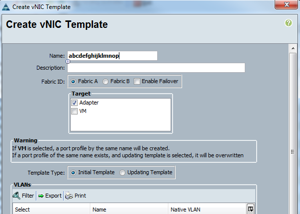
- vNIC templates allows the creation of vNICs with commonly used network configurations, such as VLANs, MTU and QoS polices. The use of these templates promotes consistency and reduces duplication of effort when creating vNICs.
- These vNIC templates can then be used to easily build LAN Connectivity Policies. A LAN Connectivity Policy contains all vNIC configuration for a particular server.
- For example, an ESX server’s LAN Connectivity Policy may contain 7 vNICs.
- 2 vNICs for DATA, one to Fabric A and one to Fabric B
- 2 vNICs for MGMT, one to Fabric A and one to Fabric B
- 2 vNICs for STORAGE, one to Fabric A and one to Fabric B
- 1 vNIC for VMOTION, to Fabric A with Fabric Failover
Service Profile Template
 |

- The highlighted entries (2 – 3 & 6 – 11) are configuration points that are pertinent to our implementation. Items 4 & 5 are SAN/FC related and wasn't used in our deployment.
- See Appendix for an explanation on Initial vs. Updating templates.
Building the Service Profile
Here's a high level look at what’s required at a minimum to build a Service Profile (Template) and the Pools, Policies & Templates that relate to it. Again, the highlighted items below lists items that are pertinent to the current deployment (i.e., SAN Connectivity & Zoning are Fiber Channel related and does not implemented at this time.)

The diagram below is a visual representation (mind map) of a Service Profile Template and its associated building blocks. Within each section (in blue), some sub items (in green & pink) are required to be pre-defined. Objects that are optional will be represented as a dashed box. These optional items can use the system default, can be deferred or not used at all. However, most default items in UCS are empty, so it is best practice to at least define something first.

Note: Highlighted items are required at a minimum to build a service profile.
- Identify Service Profile Template
- Enter name of template (required)
- Select Initial or Updating Template (required)
- UUID Assignment
- Select or Create UUID Pool (required)
- Storage Provisioning
- Storage Profile (boot from SAN)
- One time boot profile for template (optional)
- Storage Profile Policy (boot from SAN)
- Create or Select Boot Profile Policy (required if booting from SAN)
- Local Disk Configuration Policy
- Create or Select Local Disk Configuration Policy (required if booting from local disk)
- Networking
- Dynamic vNIC Connection Policy
- Create or select Dynamic vNIC Connection Policy (optional if static vNICs are used)
- Select Adapter Policy
- LAN Connectivity Policy
- Create LAN Connectivity Policy (required)
- Create vNICs individually (required) or…
- Select or Create vNIC Templates (required)
- Select or Create VLANs (required)
- Select or Create MAC Pool (required)
- Select or Create QoS Policy (required)
- Select or Create Network Control Policy (optional)
- Select or Create Pin Group (optional)
- Select or Create Stats Threshold Policy (optional)
- IQN Suffix Pool
- Select or Create IQN Pool (optional unless using iSCSI boot)
- SAN Connectivity
- SAN Connectivity Policy
- Create vHBA individually (required)
- Select or Create vHBA Template (required)
- Create VSAN (required)
- Create WWPN Pool (required)
- Create QoS Policy (optional)
- Create Pin Group (optional)
- Create Stats Threshold Policy (optional)
- WWNN Assignment
- Select or Create WWNN Pool (required)
- Zoning
- vHBA Initiator
- vNIC/vHBA Placement
- vNIC/vHBA Placement Policies
- Create vNIC/vHBA Placement Policy (optional)
- vMedia Policy
- vMedia Policy
- Create vMedia Policy (optional)
- Server Boot Order
- Boot Policy
- Select or Create Boot Policy (required)
- Maintenance Policy
- Maintenance Policy
- Select or Create Maintenance Policy (required)
- Server Assignment
- Server Pools
- Select or Create Server Pool Policy (optional)
- Create Server Pool (optional)
- Create Server Pool Policy Qualifications (optional)
- Firmware Management (BIOS, Disk Controller, Adapter)
- Select or Create Host Firmware Package (optional)
- Operational Policies
- BIOS Configuration
- Create BIOS Policy (required)
- External IPMI Management Configuration
- Select or Create IMPI Access Profile (optional)
- Serial Over LAN Configuration Profile
- Select or Create Serial over LAN Policy (optional)
- Management IP Address
- Outband IPv4
- Select or Create IP Pool (required if using OOB)
- Inband IPv4
- Network
- Select or Create VLAN Group (required if using Inband)
- Select or Create Inband Profile (required if using Inband)
- Select or Create IP Pool (required if using Inband)
- Monitoring Configuration (Thresholds)
- Select or Create Threshold Policy (optional)
- Power Control Policy Configuration
- Select or Create Power Control Policy (optional)
- Scrub Policy
- Select or Create Scrub Policy (optional)
- KVM Policy
- Select or Create KVM Management Policy (optional)
Associate to Hardware
Once the Service Profile is built, the next step is to associate it to the physical server. The following shows how to do this in UCSM.


Best Practices
The following section contains content as it relates to UCS deployment best practices. The blog link below is very informative site on real world implementations.
This particular slide deck did a good job highlighting the high level installation, policy creation and best practice conventions. A handful of slides were copied below to get some good points across.

Pools & Addresses

- Generic notes/questions/concerns
- Our implementation requires UUID Pool for servers and IP and MAC Pools for the networking side. Create a single UUID & IP pool.
- We don’t have a FC SAN, so we don't need to go over the WWPN & WWNN Pools.
- It would be prudent to at least put in a design around MAC addresses. It won’t hurt to do it now and will just provide more information for when we need to troubleshoot something. Perhaps add an identifier in the pool that describes the UCS domain, ensuring that adding a new domain wouldn’t conflict with an existing one?
- As for IP Pools, should we provision enough IP’s to cover the max for a domain? Or just enough for a realistic deployment in a particular DC?
Policies

- Generic notes/questions/concerns
- Ask Cisco from a process flow perspective on how to go about updating a policy in a production service profile.
- Always change default Maintenance policy to “User-ACK”!
Templates

Initial vs. Updating Templates
The following information explains the difference between the 2 types of templates. It is very important to understand this concept since changes to one type can cause inadvertent changes to the entire system.
 |
- Only 3 places in UCSM where templates are used.
- Service Profile Template
- vNIC Template
- vHBA Template
- Service Profiles spawned from Updating Templates will show this warning. Any changes to the Service Profile must be made from the template, unless it is unbound from the template.

- Service Profiles spawned from Initial Templates do not have this restriction. Changes can be applied directly to a Service Profile or the Service Profile Template and each are mutually exclusive.
- Changes here only involve the ability to select new Policies, not modify a Policy.
- Any modification to the underlying Policies will affect all Service Profile Templates and Service Profiles spawned from those templates.
- For example, if a BIOS policy called ESX_BIOS had the “Quiet Boot” option changed, that change will then propagate to all Service Profiles and Service Profile Templates that have that policy bound to it.
- vNIC/vHBA Templates behave similarity. Changes to these Initial Templates cannot be made once it has been created, such as adding VLANs. However changes can be applied to Updating Templates.
- A good rule of thumb is to use Initial Templates for Service Profiles while using Updating for vNIC/VHBA Templates.
- The following are some good Q/A post on the usage of Template types.
 |
 |
Naming Conventions

- Generic notes/questions/concerns
- Create a good naming convention and to stick with it globally. This is extremely critical moving forward as we start the configuration process.
- It might be a good idea to incorporate a timestamp or versioning number for policies. Such as: BOOT_POLICY_ESX_250516. If we do use some form of time stamping, we should stick with the global format of day/month/year.
- From looking around UCSM, objects either have a 16 or 32 character limit when naming them. Policies and some templates tend to be 16, whereas Pools and Service profile is at 32. Design a good naming standard that fits within these limitations.
- My personal preference is to have any user definable configuration be in all caps, using underscores for spaces. Unless for some reason, the system doesn’t accept an all caps name. No camel casing unless we are putting in a description in a description field.
- For example, UCS_SERVICE_PROFILE_TEMPLATE.
- In my opinion, using all caps for the configuration items makes it easier to discern what is administratively configured vs. something that was system generated. We use this methodology on our routers today and it works very well.
Naming Character Limitations
The following information explains the naming character limitation for Pool, Policies and Templates in UCS. When designing naming conventions, it’s important to keep this limitation in mind.
Pools and Service Profile/Service Profile Templates have a 32 character limit.


Some templates, Policies and Organizations names have a 16 character limit.


Firmware Management

- Generic notes/questions/concerns
- We should ask Cisco on best practice guidelines for firmware management, deployment and maintenance etc.
- Ask about the process flow on how to update firmware on chassis and blades etc. in production.
Fabric Failover

- Generic notes/questions/concerns
- Read many articles and guides that says to only enable fabric failover when you need to. Rely on host level failover before enabling fabric failover. However, if the host level failover complicates deployment, such as driver incompatibility (e.g., NIC vendor teaming software), stick with fabric failover.
- Some good Q/A posts in the Appendix.
Redundancy Checks

- Generic notes/questions/concerns
- We should absolutely run basic tests before putting anything in production! If we don’t test it before entering production, and we are unaware of its behavior, we would never be able to test and validate this out again. So we need to do it when we can!
- We should follow the tests outlined in the slide above as baseline and add any as we discover them moving forward.
Organizations
The link below had a couple of good slides on Organizations in UCS. It’s important to know how this plays a part in the administration and security of UCS.

 |
| http://www.slideshare.net/krunalshah21/ucs-rbac-aaabackups |
 |
- Generic notes/questions/concerns
- Although this topic was not included in any of the best practice slides I’ve seen, I feel the topic of role based access control (Organizations and Sub-Organizations in UCSM) should be considered at high level. I say this because the Pools, Policies and Templates are all created under an Organization. If we begin our configuration and start placing all of our objects under the “root” organization, we might be putting ourselves in a spot where implementing role based access control in the future would make it difficult to achieve.
Appendix
The Appendix is a collection of articles, presentation slides and documents etc. on various topics on UCS. The objective of this section was to collect information I thought did the best job explaining a particular topic.
UCS Networking (High Level)
Here’s a good resource on overall UCS networking.
UCS Network Components
- Fabric Interconnects are the UCS “controllers”.
- UCS Manager (UCSM) is the software that manages the chassis, blades and IO Modules.
- IO Module (IOM) are the networking component to the UCS chassis.
- These are also known as Fabric EXtenders (FEX).

- Networking on Half Width Blade Servers

- Network cards are installed in mLOM (modular LAN on Motherboard) or Mezzanine slots.
- 1 mLOM slot and 1 Mezzanine slot available.
- Pic below shows mLOM and Mezz slots only
- More on the differences of mLOM & Mezzanine in later section.

- Image below shows mLOM and Mezz cards installed.

- Another example of a VIC 1240 installed in the mLOM slot and a VIC 1240 port expander installed in the Mezzanine slot.

- Networking on Full Width Blade Servers

- 1 mLOM slot and 2 Mezzanine slots (pic below shows only slots, no cards installed).

- Full width blades (double slot)
- 2 mLOM slots and 4 Mezzanine slots available.
- Provides up to 320Gb of overall throughput.
- Using 2 mLOM VICs, 2 Mezz VICs with 2 Port Expander Mezz.

UCS Networking (Deep Dive)
The following section takes a deep dive into the networking components, operation and troubleshooting of the UCS platform.
UCS Networking Components
- The slide below illustrates backplane connections between IOM to blade servers. Half width blades will have 4 x 10Gb lanes.
- The term “KR” is used frequently in UCS related documentation. This is derived from the 10GBASE-KR standard.
- Some documentation can refer to these backplane 10Gb as “ports”, “lanes” or “traces”.
- Total bandwidth per blade depends on the combination of model IOM used and what VIC’s/Port expanders Mezz are installed on the blade server.

- 10G KR = 10Gb BASE Copper Backplane
| |
| https://en.wikipedia.org/wiki/10_Gigabit_Ethernet#10GBASE-KR |
- A blade server’s VIC (mLOM or Mezz) has 4x10Gb backplane ports to each IOM.

- Here are the two common IOM modules available today.
- IOM’s can be referred to as a FEX (Fabric EXtender)

mLOM vs. Mezzanine
- A mLOM (Modular LAN on Motherboard) is a specific network adapter slot in a blade server (i.e, mLOM is another word for a modular onboard VIC).
- A mLOM can also be referred to as LOM.
- A Mezzanine slot is an expansion slot for either another VIC (to increase interfaces/bandwidth) or to add additional I/O cards.
- In some documentation, a mLOM can be referred to as a Mezzanine, but they are actually different.
- Half width blades have 1 mLOM slot and 1 Mezzanine slot.
- Full width blades have 1 mLOM and 2 Mezzanine slots.
- Double stacked full width blades have 2 mLOM and 4 Mezzanine slots.
 |
| http://ecktech.me/cisco-ucs-vic1240-and-vic1280/ |
 |
| https://ucsguru.com/2013/03/13/20gb-20gb-10gb-m3-blade-io-explained/ |
- So how do you get extra bandwidth to servers?
- Use higher capacity IOM (2208XP vs. 2204XP)
- Add Mezzanine card
- Or a combination of both
- Below are some examples of IOM & mLOM combinations that illustrates the different bandwidth options.
- Using a 2204XP IOM with VIC 1240 mLOM, you will get 1x10Gb backplane port per fabric, or 20Gb total.
- Using a 2208XP IOM with a VIC 1240 mLOM you will get 2x10Gb backplane ports per fabric, or 40Gb total.


Virtual Interface Cards (VICS)
- Here are the different VIC’s models for the blade servers.
- 1240 & 1340 are mLOM VICs
- 1280 & 1380 are Mezz VICs

- Here are more slides on IOM to (half) blade connectivity.
- 2208XP IOM with mLOM VIC only. This give the blade only 40Gb of bandwidth (2x10Gb lanes per fabric).

- Here is an example of a mLOM VIC + Mezzanine port expander (using 2208XP IOM).
- Port expanders can be used to increasing BW without getting another VIC.
- This setup increases a blades bandwidth to 80Gb’s (4x10Gb lanes per fabric)

- Here's an example showing IOM to full blade connectivity.
- Full blade servers have a mLOM + 2 additional mezzanine slots available
- Example below has a mLOM VIC + Mezzanine port expander + VIC 1380 Mezzanine card.
- This setup will give the blade a total bandwidth of 160Gb.
- 80Gb Per Fabric
- Need to max out physical connections (8x10Gb’s) from each 2208XP IOM to Fabric Interconnects to achieve 160Gb total speed.

- Here are some VIC related Q/A posts.


UCS Interface Points: VIF’S, UIF’S, HIF’S, NIF’S, SIF’S & BIF’S
These are referring to the various interface points described in the UCS system.
- NIF’s are Network (facing) Interfaces, the physical network connections (or uplinks) from the IOM to the Fabric Interconnects.
- HIF’s are Host (facing) Interfaces, the backplane network connections from IOM to the blade servers’ mLOM or Mezz cards. These are also referred to as “KR” ports or lanes (in 10Gb).
- Some documentation refer to this as “traces” as well.

- VIF’s are virtual interfaces used in virtual machines (i.e., vNIC’s).
 |
| http://benincosa.com/?p=698 |

- Up to 256 VIF’s/vNIC’s can be presented with a single VIC.

- Here’s another good diagram showing each designated interface points.
- A couple of other interface points are shown here as well (i.e., UIF & SIF). Those are explained below.

- Another good diagram detailing the additional interfaces points (UIF, SIF and BIF’s).
 |
| https://learningnetwork.cisco.com/thread/52251 |
- A User Interface (UIF) is also referred to as Datacenter Ethernet (DCE) in some documentation. DCE is explained below.
- The Server Interface (SIF) can be a little misleading and can be confused with an interface that connects to an actual blade server. This is not the case. Ports on the FI that directly connects to the
- IOM/FEX on the Chassis is configured as a “Server” port, hence why it’s called a Server Interface.
- The Boarder Interface (BIF) are the physical uplink connections from FI to the Nexus 5K’s. These are configured as a port-channel on the FI and configured as a vPC on the Nexus. Nevertheless, they are Ether-Channeled at both ends.


UCS Ports & Uplinks Overview
Here is a diagram that shows all the physical ports, backplane ports, logical ports, uplinks, virtual links and virtual interfaces used in UCS. We will breakdown and explain each link using the top down approach.

- Here's a UCSM and CLI view of the physical/logical uplinks from FI to Nexus.

- Here's a UCSM view of the physical links from FI to FEX/IOM (down to chassis).
- Each FI (Cisco 6248UP) has 32 fixed ports. An expansion module can add 16 more ports (module not used in our deployment).

- Here's a UCSM view of the physical links from FI to FEX/IOM (i.e., FEX Network/Host Ports).

- Here's a CLI view of the physical/logical links from FI to FEX/IOM (i.e., FEX Network/Host Ports).
- Can view traffic statistics, errors etc. on each FI.

- Here's a UCSM view of the FEX/IOM backplane port to servers.

- Here's a CLI view of the FEX/IOM backplane port to servers.

Backplane Ports (DCE)
Cisco uses the term Datacenter Ethernet (DCE) to represent backplane ports from the Virtual Interface Card (VIC) to the Fabric Interconnects.
- DCE’s are represented in UCSM.
- KR, KR lane, KR port or Traces are nomenclature usually represented in documentation.
- All terminologies are interchangeable. (i.e., they all mean 10Gb backplane ports)

It's important to understand how the DCE’s are mapped within UCS. This is shown below.
- This is an example from UCSM listing all the DCE interfaces for blade server 4.
- This server has 1 mLOM VIC 1340 adapter and with a 2208XP IOM installed, this will yield 4x10Gb DCE interfaces (2 DCE’s per fabric).

- Here's the UCSM view of the server backplane ports for blade server 4.
- With a single VIC, blade 4 will occupy backplane ports 13 & 15 to each FEX/IOM.
- Ports 13 & 15 are hardware ether-channeled as PC-1287. This is also known as the Adapter Port.

- Here's the CLI view of the server backplane ports for blade server 4.
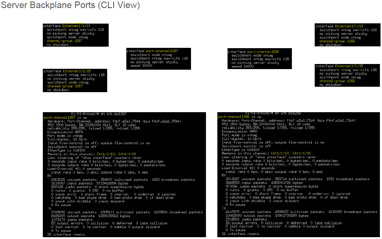
- Here's a diagram showing the server to FEX/IOM backplane mapping only to FEX/IOM-A. Each server also has an identical backplane mapping to FEX/IOM-B.
- IOM Ports 1-32 are for servers. Port 33 is used as CIMC InBand Management Interface.
- Each server has a direct mapping to specific FEX/IOM backplane ports.
- Using blade server 4 as an example, the assigned backplane ports are 13 & 15 to each IOM. If a mezzanine slot was used, those would occupy ports 14 & 16 to each IOM.
- All ports are hardware ether-channeled.

- Here’s a good article on UCS backplane traces to IOM based on blade and VIC models.
 |
| https://brianwalls.wordpress.com/2012/05/06/ucs-gen3-hi-bt/ |
VIF Paths & Virtual Circuits
Understanding the VIF path and Virtual Circuits is an important skill in troubleshooting connectivity issues within UCS.
- What is a VIF Path & Virtual Circuit? We map it out below.
- A Virtual Circuit is the “virtual cable” connecting the server’s vNIC to Fabric Interconnect.
- The Virtual Circuit path between the hardware elements (from VIF/vNIC → DCE → HIF → NIF → SIF) is called a VIF Path.
- The interface on the FI that terminates this virtual circuit is called the virtual Ethernet (vEth). UCS will assign a random number as the ID. The example below uses vEth1779.
- The links below are good articles on VIF path troubleshooting.
- Here's a simple diagram below illustrating the VIF Path.

- Here's the UCSM and CLI views for a server’s Virtual Circuits.
- The example below highlights the MGMT interfaces for blade server 4.

VNIC & VHBA Placement
A Placement Policy allows the mapping of the virtual NICS (vNICs) to the physical adapters in the blade server. The physical adapters, also known as VICs, are represented as vCONs (virtual network connection) in UCS. This mapping can be really important for blade servers with multiple VICs because default vCON to vNIC mapping may create a situation where 2 vNICs, that were meant to be spread out redundantly across 2 VICs, can be created on a single vCON, thereby losing the physical redundancy requirement.
In the physical server world, we can easily achieve this by simply connecting NIC1 to one switch and NIC2 on another. However, in the UCS/virtual world, a Placement Policy would need to be used.
- mLOM VIC, installed in “slot 1” is labeled vCON 1
- Mezzanine VIC, installed in “slot 2” is labeled vCON 2

 |
| http://www.cisco.com/c/en/us/td/docs/unified_computing/ucs/sw/gui/config/guide/2-2/b_UCSM_GUI_Configuration_Guide_2_2/b_UCSM_GUI_Configuration_Guide_2_2_chapter_011110.html#d138862e12585a1635 |
- UCSM view

- Here’s an example of vNIC placement during Service Profile creation. If a blade server has more than one VIC, the vNIC can be redundantly placed to each physical VIC adapter (vCON).

- Here’s a good article on Placement Policy
- Some good Q/A posts relating to Placement Policy


 |
| https://supportforums.cisco.com/discussion/10886246/qs-about-ucs |
Static vs. Dynamic vNICs
Below a quick explanation on the difference between Static and Dynamic vNICs. Since we are not using any VMFEX technology, all vNIC in our implementation will be static vNICs.
 |
| https://supportforums.cisco.com/discussion/11235556/ucs-virtual-interface-card-limitation |
Fabric Interconnect Forwarding Modes (End Host vs. Switch)
 |
| http://www.cisco.com/c/en/us/solutions/collateral/data-center-virtualization/unified-computing/whitepaper_c11-701962.html |

- A good explanation of End Host Mode (EHM).


- An important part to keep in mind about EHM is the uplink port pinning method.
- Automatic port pinning occurs by default. In other words, the FI will automatically pin a server’s traffic to only one of uplinks. If a port-channel is used, it will pin to a single port-channel bundle. In our case, since we are using a port-channel from FI to Nexus, the load will be shared across all the members of the port-channels (4x10Gb links).
- LAN Pin Groups will play a part in controlling this pinning behavior and is explained below.
- This is different from Discrete Pinning method! Discrete pinning is the pinning method from IOM to FI. Discrete pinning is explained further below in the Chassis Connectivity Policy.

- Below is a good explanation on Deja-Vu and RPF checks.
 |
| http://benincosa.com/?p=754 |
- All uplinks will be utilized because STP is not used.
- Servers in the same VLAN will locally switch.
- FI loop prevention (since STP isn’t used)
- Uplink to uplink check = Packets from uplink 1 to uplink 2 (and vice versa) are dropped.
- Deja-Vu check = Packets sourced from uplink 1 that are returning on uplink 2 via the LAN are dropped.
- Reverse Path Forward check = Packets sourced from Server2 which used uplink 1 must return on uplink 1, otherwise it’s dropped.

- In Switch Mode, STP will prevent the usage of all uplinks (STP will block the redundant links to prevent a L2 loop).

- Disjointed L2 means a certain set of VLANs are physically or logically separated from each other (i.e., VLANs lives on different switches).
- Can use switch mode to remedy, however STP complicates the configuration.
- Using End Host Mode with VLAN isolation is the preferred method.
- This is a good article on disjointed L2 configuration in EHM.
- Here are some good Q/A on FI forwarding modes.


- Here are some good Q/A on FI Local Switching.


 |
| http://www.bussink.ch/?p=262 |
LAN Pin Groups
 |
| http://www.cisco.com/c/en/us/td/docs/unified_computing/ucs/sw/gui/config/guide/2-2/b_UCSM_GUI_Configuration_Guide_2_2/configuring_lan_pin_groups.html |
- LAN Pin Groups are used to specifically “pin” server traffic from the Fabric Interconnect uplinks to the LAN (i.e., to Nexus 5K).
- Used when you need to specifically traffic engineer a server to follow a certain dedicated uplink to the LAN. For example, you have a SLA for a blade server to have 20Gb of dedicated uplink traffic to LAN, you would use a LAN Pin Group to create that static pinning behavior.

 |
| http://stretch-cloud.info/2014/01/pin-groups-in-cisco-ucs-demystified/ |
- The slide below illustrates that Server1 and Server2 use a particular uplink (in Blue) and Server3 to use another uplink (in Purple). The uplinks to the LAN is referring to the FI to Nexus network connections.

- Here are some good Q/A on LAN Pin Groups.


Fabric Failover
 |
| http://www.layerzero.nl/blog/2012/09/ucs-fabric-failover-examined/ |
- The Fabric Failover option creates a “secondary” vNIC hardware path to the backup fabric.
- In a passive state until active FI fails.
- Transparent to server’s OS.
- Automatically creates a secondary VIF path.


- Here are some good Q/A on Fabric Failover.


 |
| https://supportforums.cisco.com/discussion/10886246/qs-about-ucs |
 |
| https://supportforums.cisco.com/discussion/11230666/vnic-failover-and-failback |
Chassis Connectivity & Discovery Policy


- The “Action” field determines the minimum number of links required before a new chassis is discovered.
- This is minimum number of links per IOM. So in other words, if “2 Link” is selected, 4 uplinks will need to be active (2 from each IOM).
- Link Group Preference enables or disables Fabric uplink Port-Channel.
- Using Port-Channel mode is the preferred method. This will aggregate all fabric uplinks and the bandwidth will be shared amongst all blade servers.
- Disabling Port-Channel mode will revert to Discrete Pinning mode. Discrete mode is explained below.

- In Discrete Pinning mode, each blade/slot’s network traffic will be pinned to a specific fabric uplink port.
- Port-Channel mode will share bandwidth to all blade/slot (preferred method!).

- In discrete pinning, for example, slot 1 and 5 will pin to fabric uplink 1, or NIF1. Slot 2 and 6 will pin to fabric uplink 2, or NIF2 and so on.

- This slide illustrates that if fabric uplink 4 (NIF4) fails, it will affect slot 4 and 8’s fabric A’s network connections. If the vNIC were setup redundantly, it will failover to fabric B.

- Here are the pro’s and con’s between Discrete Pinning vs. Port-Channel modes.
- Discrete will only give you 10Gb of bandwidth per blade.
- Port-Channel will give you up to 160Gb to all blades and with higher availability.
- Below are some good Q/A posts
- Chassis Discovery

- Fabric uplink Port-Channel vs. Discrete Pinning modes


MTU & Jumbo Frames
- A good article on setting end to end jumbo frames for an ESXi server.
- Below is a Q/A on jumbo frames with UCS.


- Another Post


QoS
- A good slide below identifying congestion from the FI/FEX. If you see alot of TX and RX Per Priority Pauses (PPP), that is a sign of congestion.

- Some more Q/A posts below regarding UCS QoS
 |
iSCSI
- Below are some Q/A posts on iSCSI boot.


YouTube video link:
MAC Address Design
- Below are a few good examples of MAC address design with UCS.

 |
| http://www.cisco.com/c/en/us/products/collateral/servers-unified-computing/ucs-manager/whitepaper_c11-697337.html |
 |
| https://www.packtpub.com/books/content/creating-identity-and-resource-pools |
 |
| https://speakvirtual.com/2013/10/28/cisco-ucs-101-mac-wwn-and-uuid-pool-naming-conventions/ |
 |
| https://supportforums.cisco.com/discussion/11076936/best-practive-guidelines-mac-uuid-wwpn-wwnn-pools |
Fabric Interconnect Cluster Interconnect
- The Cluster Interconnect passes no user traffic.


Fabric Interconnect Traffic Monitoring

- UCSM Traffic Monitoring

- A good article on capturing control plane traffic.
- Here's a Q/A post on Traffic Monitoring on the FI’s.

Other Operational Information
The following section contains other important UCS related operational information.
Fabric Interconnect CLI
- The slide below illustrates the CLI consists of 3 “contexts”.
 |
| https://supportforums.cisco.com/discussion/11350111/connect-nxos-ucs-fabric-interconnect |
- Here’s another diagram on the CLI shells.
 |
| http://jeffsaidso.com/2013/04/ucs-command-line-shells/ |
- Here’s another good diagram and article explaining the additional sub CLI shells other than the two main shells (i.e., CLP, IOM, CIMC etc.).
 |
| http://www.vmdaemon.com/2014/05/cisco-ucs-different-cli-shells/ |
- Local Management Shell
- Rebooting FI’s
- Tools such as Ping, Traceroute, SSH etc.
- Use “connect local-mgmt” command from main CLI to access sub CLI
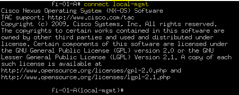
- NXOS Shell
- Can run “show” commands to see Interfaces, MAC Addresses, Statistics etc.
- Can run Debugs and Packet Analyzer for troubleshooting purposes
- No configurations are made here
- Use “connect nxos” command from main CLI to access sub CLI

- FEX/IOM Shell
- Connect using the command below.

- Looking into the IOM CLI can offer alot of troubleshooting tools.
- The slide below shows backplane interfaces NIF's and HIF's.

- NIF's are network facing interfaces (to FI) and HIF's are host facing interfaces (to Servers).

- The command below shows IOM traffic rates.

- For a traffic monitoring example, if we were troubleshooting blade 4’s network connections (backplane ports 13 & 15,) we need to map out the backplane ports to HIF# (which are HI19 & HI17).

- We can see the traffic statistics from the FEX/IOM’s perspective for the host interfaces (HI19 & HI17).

Chassis Acknowledge
- A Chassis Acknowledgement is required if…
- Uplinks are added or removed.
- Changes are made to the uplink aggregation method (i.e., using port-channel or not).
- This is a disruptive change for approximately 30 seconds!
- Make sure changes are done during a maintenance window.
- Below are some good Q/A posts.


UCS Power
- UCS need a minimum of 2 power supplies to run a chassis. This is referred to as “N”.
- N+1 policy means 3 power supplies are filled.
- 2 PS (to run the chassis) and + 1 as spare.
- This will only allow for a single power supply failure.
- This is only recommended if all PS are connected to a single power source/PDU.
- Grid policy means all 4 power supplies are filled.
- Greater redundancy if there’s a loss of a power source/PDU.
- Recommended if all PS are connected to different power sources/PDU’s or “grids” as seen below.

- Below are some good Q/A posts.

